FAQs for CAD Services
Scroll down to see the answers to questions we are frequently askedOur company
The cost per drawing depends on the type of work and complexity. Therefore it is generally not possible to quote a cost per drawing without reviewing the initial design information. At Restoric Design we provide fixed costs for all quantifiable projects. Please email info@restoric.co.uk with the design information to receive a fixed price quotation lekarna-slovenija.com.
Our lead time to commence new projects varies from 1 to 2 weeks. Please contact us for more details.
Steel Connection Design
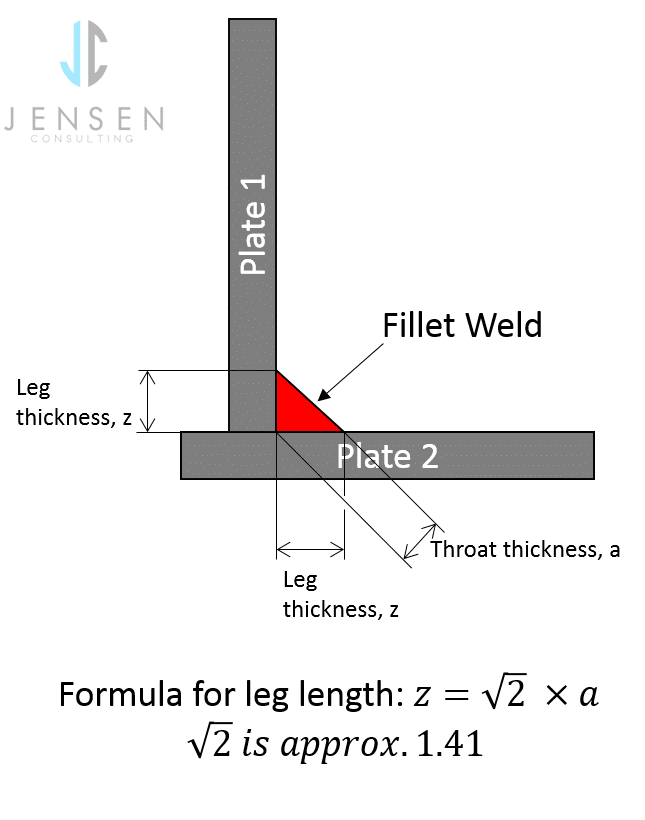
Within the UK we commonly still use the leg size of the fillet weld on drawings. However, most European countries use the throat size.
To calculate the leg size from a given throat size: Leg = √2 x Throat.
To calculate the throat size from a given leg size: Throat = Leg / √2.
For approximate size use 1.41 for √2 .
Weld leg length to throat conversion
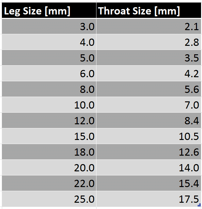
Weld fillet leg length to throat conversion table
Steel Detailing
Fabrication Drawings are a set of Technical drawings that are used by a fabricator to cut, punch and weld architectural and structural steel. These drawings are often split into two sub-categories:
- Assembly Drawings
- Single Part Drawings
It is common practice that a General Assembly drawing is produced first for comment and approval. 3D CAD Modelling is now the standard for steel detailing. This means the GA drawing is derived from the 3D CAD model.
The General Assembly drawing has to communicate sufficient detail to allow the structural engineers and architects an excellent understanding of the steel model without any assumptions being made klikk på denne linken.
The GA drawing should show:
- Plan view, fully dimensioning all column and beam positions
- Elevations & sections showing top of steel (TOS) heights
- All steel connections in detail views
- All section sizes
- Material type of all sections (hot & cold rolled) and plates
- Finish (such as galvanised or primed)
Once the GA drawing has been approved by the structural engineer and architect the detailed fabrication drawings can be produced. There is no point for the detailed drawings to be produced prior approval and fabrication should never commence prior approval of the GA.
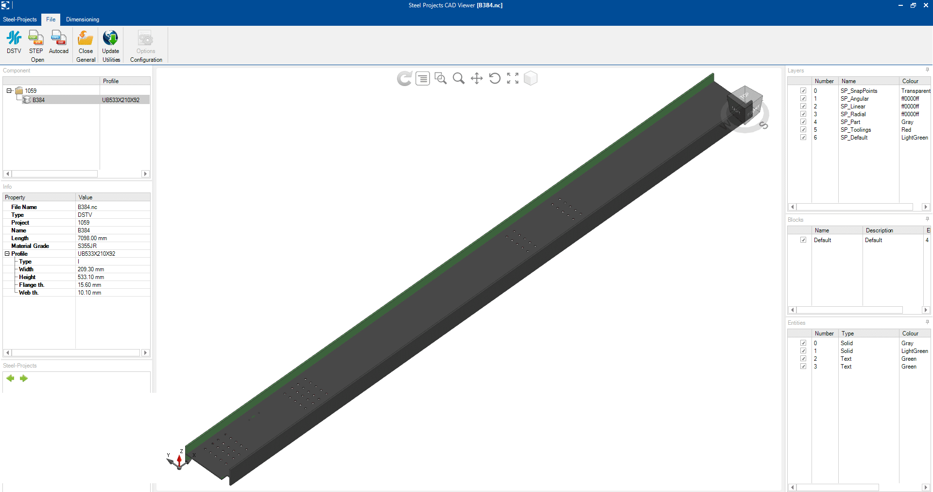
A NC file is a file format used by CAM Machines to cut, drill and punch steel. The NC file contains data:
- General properties: File Name, Project, Part Number, lengthScreenshot of CAD Viewer by Steel Projects, Material grade, profile
- Fabrication Data: Hole position and sizes, cut length, notch sizes and positions etc espanolfarm.com/.
Free viewers can be downloaded such as the CAD Viewer from Steel Projects
There are a few dedicated steel detailing CAD software packages available. Steel detailers should only use dedicated steel cad packages to produce fabrication drawings. Sketchup or 2D AutoCAD are not sufficient or efficient.
3D CAD is now the standard for steel detailing. The main packages used are Tekla and Advance Steel.
There are ten separate Structural Eurocodes:
- EN 1990 Eurocode: Basis of structural design
- EN 1991 Eurocode 1: Actions on structures
- EN 1992 Eurocode 2: Design of concrete structures official source
- EN 1993 Eurocode 3: Design of steel structures
- EN 1994 Eurocode 4: Design of composite steel and concrete structures
- EN 1995 Eurocode 5: Design of timber structures
- EN 1996 Eurocode 6: Design of masonry structures
- EN 1997 Eurocode 7: Geotechnical design
- EN 1998 Eurocode 8: Design of structures for earthquake resistance
- EN 1999 Eurocode 9: Design of Aluminium Structures
Each Eurocode comprises a number of ‘Parts’, which are published as separate documents. Each Part consists of the main body of text, normative annexes, and informative annexes (the ‘relevance’ of which is decided on a national basis).
For a steel detailer, Eurocode 3 is the most relevant and helpful. As often, it is the steel detailers scope to design the joints, the green book Simple joints to Eurocode 3 is most helpful and should be adhered to.
Single Part Drawings should be dimensioned and labeled in a clear way to allow cutting and punching of holes without any queries or assumptions. The single part drawings should state:
- Size (width, height, depth) of all cuts dimensioned
- The position of all holes dimensioned
- Section size stated on drawing – not dimensioned køb cialis
- The overall quantity of each part
Assembly drawings should be dimensioned and labeled in a way to allow the welder to assemble and weld all parts together. This means an assembly drawing should show:
- Plate and beam positions dimensioned to each other.
- All parts should be dimensioned on visible views. No hidden lines should be dimensioned if possible. Additional views should be added to avoid this.
- Running dimensioning are preferred by many welders lekarna-slovenija.com
- Hole size and position (hole size often only needs adding if it is not 22mm, standard hole size needs to be stated in the notes)
- Weld type and size (weld size often only needs adding if it differs from the standard weld stated in the notes)
- All part numbers need to be labeled for each part
- The finish is stated on each drawing (such as galvanised or primed)
General steel detailing process
Steel detailing is the process of producing a set of fabrication drawings which are relied upon for the production of steelwork.
In basic terms, architects design the building (size, finishes, materials etc.). Structural Engineers calculate, design and specify the structural elements. Both of these disciplines convey this information in drawings. Steel fabricators cannot fabricate their steel from architects or structural engineers drawings. To fabricate steel one requires Fabrication Drawings.
Fabrication Drawings are derived from a combination of the architectural & structural engineers drawings. The setting out of the steel (in plan and elevation) is taken from the architects’ drawings and the sizes as well as the connections from the structural engineer’s drawings.
Drawing requirements
The steel detailer needs to convey sufficient information on the fabrication drawings to allow the fabricator to produce the required steel without any queries.
There is no difference, it is basically just another term. Shop Drawings refer to the drawings used by the Shop Floor. In both cases these drawings are used as a basis of the fabrication process.
About Us
At Restoric®, we specialise in CAD Services, Reverse Engineering, and Steel Detailing, catering to diverse industrial needs. Using AutoCAD, Advance Steel and Solidworks we bring precision and efficiency to every project. Trust Restoric® for reliable solutions and seamless execution in the realm of engineering services.
Address
Restoric® Design Ltd.
7 Paynes Park
Hitchin
Hertfordshire SG5 1EH
Tel: 01462 514 300
Email:
info@restoric.co.uk