Shop drawings are an essential part of the mechanical construction process. They offer an intricate design to follow that can be easily understood and executed using the right dimensions and functions, working almost like a language between two engineers to understand each other and visualise the process. In this guide, we’ll outline the steps toward making the most effective mechanical shop drawings.
Choose a medium
The first step to producing a mechanical shop drawing is to choose the medium that you will be using. If you are proficient at drawing using pencil and paper, you may turn to this immediately, especially if you have a clear image in your head of what you want the mechanical part to look like and wish to get this visualised in the most simple way. This is most likely to work for small and/or simple plans.
However, complicated designs or mechanical parts will probably require the use of Computer-Aided Design (CAD). You may need to spend some time learning how to use the software or source a company to do it for you. Although a more expensive option, this has a host of benefits, such as making it easier to create crisper designs with optimised measurements rather than relying on handwritten notes. 2D drawing software is often sufficient for smaller jobs in the shop drawing process.
Create schematics drawings
In mechanical shop drawings, schematics are essential. Schematic drawings are detailed diagrams of an electrical or mechanical system. They describe how something works and how individual parts interface, so without it, there is no clear view of how the mechanics would function. As we said above, you could draw this by hand or you could use 2D drafting on a CAD system to make the process more streamlined and accurate.
Create M&E Drawings
Another key element to a mechanical shop drawing is M&E or MEP drawings. These are shop drawings used for the installation of the mechanical component, ensuring that it’s compatible and can be integrated properly for its intended use. Like schematic drawings, the most straightforward way to produce these is via CAD 2D drafting.
Integrate 3D modelling
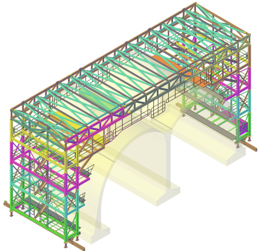
As technology advances, schematic drawings and MEP drawings are being increasingly developed in 3D using Building Information Modelling. If you have the capacity, 3D modelling can be helpful for a more detailed and overarching design that has better visuals and attention to detail than 2D drawing.
It may also be used as the last stage of mechanical shop drawings to bring all of the components together and design what the finished product will look like. In particular, it can be useful for producing different views of the end goal, such as axonometric views, orthographic projection and assembly drawings. Some essential views for mechanical shop drawings can just as easily be produced with less expensive and complicated 2D drawings, however, such as sectional views.
Include dimensions
No matter the technique you choose, it is vital that when creating mechanical shop drawings you clearly present dimensions. Always indicate feature sizes with arrows that do not intersect each other and only indicate a dimension once on a drawing. This can be done easily by hand as well as on any CAD system. Remember, even when using CAD, to include tolerances, indicating what variability with each dimension is expected and acceptable. Errors can be made even on computers, so having a margin for error is essential.
For help with mechanical shop drawings using CAD, get in contact with Restoric Design today by calling 01462 514 300.


