

A machine drawing (manufacturing drawing) is a detailed illustration produced by the CAD Drawing Office for the machine shop. The machine drawing will give the machinist sufficient detail (no more than required to eliminate confusion) to produce the part without any queries.
The integration of 3D CAD has shown demise in the quality of machine drawings. This is mainly due to the failing of the education system concentrating on 3D CAD modelling and disregarding the importance for good quality manufacturing drawings.
The draughtsman must be able to appreciate the significance of every line on a machine drawing. He must also understand the basic terminology and vocabulary used in conjunction with machine drawings.
Machine drawings of components can involve any of the geometrical principles and constructions described in these articles in addition the accepted drawing standards covered by BS8888.
The image illustrates many features found on machine drawings and the notes which follow given additional explanation and revision comments.
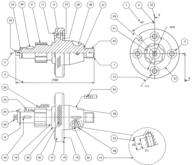
Example of a Machine Drawing/Manufacturing Drawing
- Angular dimension — Note that the circular dimension line is taken from the intersection of the centre lines of the features.
- Arrowheads — The point of an arrowhead should touch the projection line or surface, it should be neat and easily readable and normally not less than 3 mm in length.
- Auxiliary dimension — A dimension given for information purposes but not used in the actual manufacturing process. .
- Boss — A projection, which is usually circular in cross-section, and often found on castings and forgings. A shaft boss can provide extra bearing support, for example, or a boss could be used on a thin cast surface to increase its thickness in order to accommodate a screw thread.
- Centre line — Long-dashed dotted narrow line which is used to indicate the axes of holes, components and circular parts.
- Long-dashed dotted wide line — This is used to indicate surfaces which are required to meet special specifications and which differ from the remainder of the component.
- Chamfer — A chamfer is machined to remove a sharp edge. The angle is generally 45°. Often referred to as a bevelled edge.
- Circlip groove — A groove to accommodate a circlip. A circlip may be manufactured from spring steel wire, sheet or plate which is hardened and tempered and when applied in an assembly provides an inward or outward force to locate a component within a bore or housing.
- Clearance hole — A term used in an assembly to describe a particular hole which is just a little larger and will clear the bolt or stud which passes through.
- Counterbore — A counterbored hole may be used to house a nut or bolt thread so that it does not project above a surface. It is machined so that the bottom surface of the larger hole is square to the hole axis.
- Countersink — A hole which is recessed conically to accommodate the head of a rivet or screw so that the head will lie at the same level as the surrounding surface.
- Section plane or cutting plane — These are alternative terms used to define the positions of planes from which sectional elevations and plans are projected.
- Dimension line —This is a narrow continuous line which is placed outside the outline of the object, if possible. The arrowheads touch the projection lines. The dimension does not touch the line but is placed centrally above it.
- Enlarged view — Where detail is very small or insufficient space exists for dimensions or flotes then a partial view may be drawn with an increased size scale.
- Round — This term is often used to describe an external radius.
- Fillet — This is the term given to the radii on internal corners. Often found on castings, where its function is to prevent the formation of stress cracks, which can originate from sharp corners. Where three surfaces meet on a casting the fillet radii will be spherical.
- Flange — This is a term to describe a projecting rim or an edge which is used for stiffening or for fixing. The example here is drilled for countersunk screws.
- Hatching — Note that cross hatching of the component at the section plane is performed with narrow continuous lines at 45°. Spacing between the hatching lines varies with the size of the component but should not be less than 4 mm.
- Hidden detail — Indicated by a narrow dashed line. Dashes of 3 mm and spaces of 2 mm are of reasonable proportion.
- Knurl — A surface finish with a square or diamond pattern. Can be used in a decorative manner or to improve grip.
- Leader line — Leaders are used to indicate where dimensions or notes apply and are drawn as narrow continuous lines terminating in arrowheads or dots. An arrowhead should always terminate on a line; dots should be within the outline of the object.
- Local section — A local section may be drawn if a complete section or a half section is inconvenient. The local break around the section is a continuous narrow irregular line.
- Machining centre — An accurately drilled hole with a good finish at each end of the component which enables the work to be located during a machining operation on a lathe.
- Machining symbol — If it is desired to indicate that a particular surface is to be machined, without further
- Surface finish — If a surface is to be machined and a particular quality surface texture is desired then a standard machining symbol is added to the drawing with a number which gives the maximum permissible roughness expressed numerically in micrometres.
- Surface finish — If maximum and minimum degrees of roughness are required then both figures are added to the machining symbol.
- Pitch circle diameter — A circle which passes through the centres of a series of holes. The circle is drawn with a long dashed dotted narrow line
- Recess — A hollow feature which is used to reduce the overall weight of the component. A recess can also be used to receive a mating part
- Slot — An alternative term to a slit, groove, channel or aperture
- Spigot — This is a circular projection which is machined to provide an accurate location between assembled components.
- Splined shaft—A rotating member which can transmit a torque to a mating component. The mating component may move axially along the splines which are similar in appearance to keyways around the spindle surface.
- Square — Diagonal lines are drawn to indicate the flat surface of the square and differentiate between a circular and a square section shaft. The same convention is used to show spanner flats on a shaft.
- Taper — A term used in connection with a slope or incline. Rate of taper can also define a conical form.
- Taper symbol — The taper symbol is shown here in a rectangular box which also includes dimensional information regarding the rate of taper on the diameter.
- External thread — An alternative term used for a male thread. The illustration here shows the thread convention.
- Internal thread — An alternative term for a female thread. The illustration here shows the convention for a female tapped hole.
- Undercut — A circular groove at the bottom of a thread which permits assembly without interference from a rounded corner. Note in the illustration that a member can be screwed along the M20 thread right up to the tapered portion.
- Woodruff key — A key shaped from a circular disc which fits into a circular keyway in a tapered shaft. The key can turn in the circular recess to accommodate any taper in the mating hub.
- Key — A small block of metal, square or rectangular in cross-section, which fits between a shaft and a hub and prevents circumferential movement.
- Keyway — A slot cut in a shaft or hub to accommodate a key.