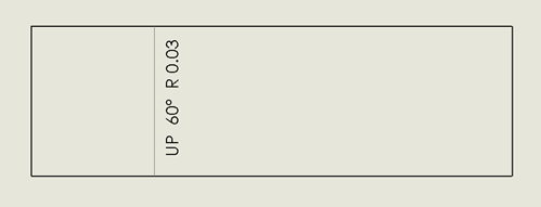
An important part of sheet metal drawings is to include a ‘flat pattern’ of the fabrication. SolidWorks will automatically show bend lines but this isn’t always the case. The problem lies with the visibility of the relevant sketches. SolidWorks creates and uses ‘bend lines’ automatically upon the generation of a sheet metal feature, such as a base flange.

       bend-lines-1 bend-lines-2

Two things must be checked to ensure the bend lines are visible in the drawing:

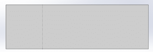
1)      Are ‘sketches’ made visible in both the model and drawing view?
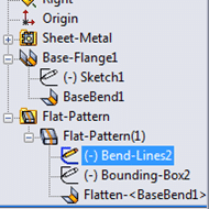
2)      Is the ‘bend-lines’ sketch under flat pattern set to ‘shown’ when unsuppressed?

 bend-lines-3

If the bend lines still fail to show after these corrections then their maybe a graphical or model errors which need to be investigated and corrected prior to this. I hope you found this solidworks tutorial useful – don’t forget to share it with your colleagues and friends!

Related Articles

What is historic building information modelling?

Meta Description: Learn about the basics of historic building information modelling and how this technology can help with restoration projects. The preservation of historic buildings and structures is a complex and challenging endeavour. To ensure the long-term...

How to make mechanical shop drawings

Shop drawings are an essential part of the mechanical construction process. They offer an intricate design to follow that can be easily understood and executed using the right dimensions and functions, working almost like a language between two engineers to understand...

How to check fabrication drawings

Fabrication drawings are essential in the fabrication industry as they guide all structural construction processes. Accuracy in the drawings is therefore paramount. This article shows you how to check fabrication drawings to ensure they serve their intended purpose...