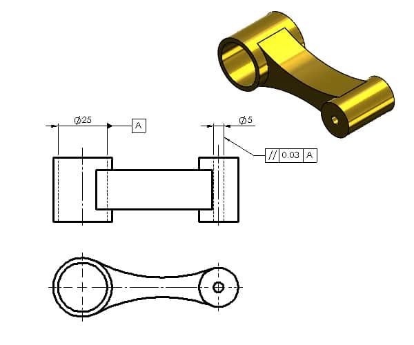
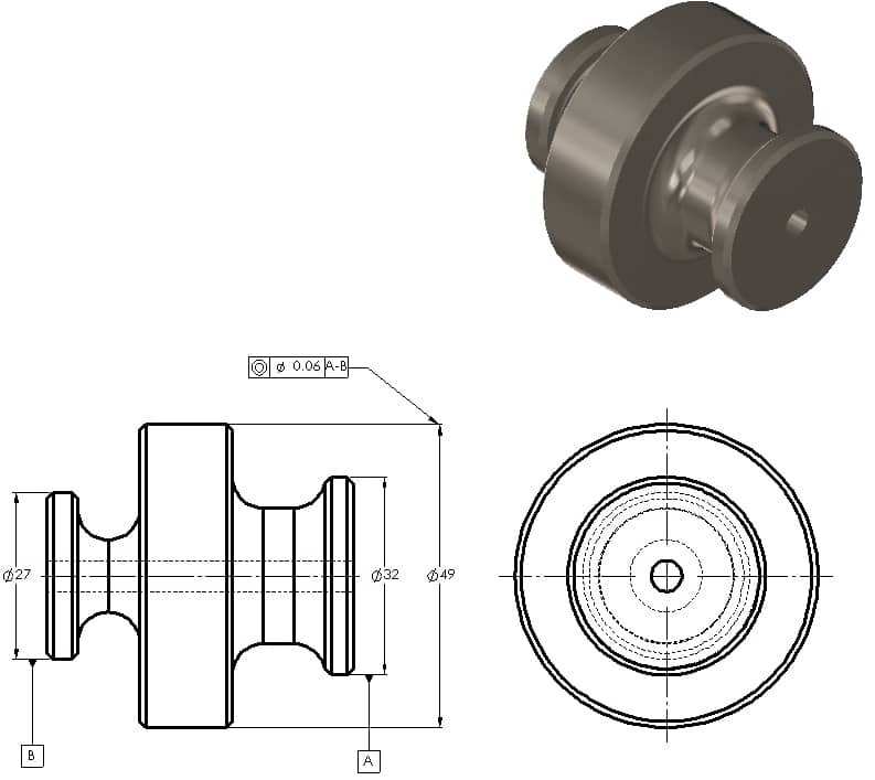
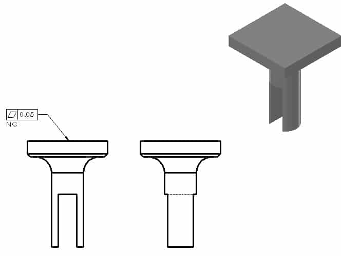
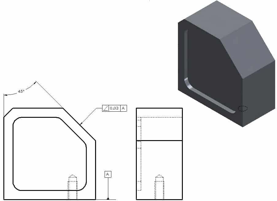
Geometrical Tolerancing can be best described as a language of symbols placed on technical drawings to adequately define the allowable variation of part geometry.
Geometrical Tolerancing in its various forms has been around for nearly fifty years and is now widely used and accepted throughout manufacturing industry. It has developed to become a valuable tool essential for meeting the high standards demanded by todays modern high technology workplaces publisert her. The scope of Geometrical Tolerancing spreads across the board and is a system that can be applied equally to the control of small geometry like electronic components right through to very large geometry used, for example, by companies manufacturing aircraft components.
An accurate and respected communication system of this kind is essential to ensuring
that in todays highly competitive global markets a successful end product can be assured giving greater confidence throughout the manufacturing industry.
The current internationally accepted standard in Geomtrical Tolerancing is BS EN ISO 1101:2013: Geometrical product specifications (GPS). Geometrical tolerancing. Tolerances of form, orientation, location and run-out.
Engineering drawing practice (technical drawing) can be categorised into three sections:
1. General Principles
This is concerned with technical drawing layout, scale, line types, text, sections, projection and how to show common features.
2. Dimensioning and size tolerancing
This is concerned with the principles of dimensioning and how to apply size tolerances (not geometrical tolerances) to technical drawings. It also covers machining requirements and surface texture.
3. Geometrical tolerancing
This is concerned with controlling form, location and orientation of a feature (axis, plane, surface, hole etc.). This is done by applying the principles of geometrical to engineering drawings with at the aid of geometrical symbols.
What is a Geometrical Tolerance?
A geometrical tolerance is the maximum allowable variation of form or position of a feature. This is controlled by defining the size and shape of a tolerance zone. The specified part of the feature must be within this tolerance zone.
When to use a Geometrical Tolerance?
- The size tolerance of a dimension has a certain amount of control over form and attitude, but if a better degree of control is required then geometrical tolerances should be used
- Position of a feature is also controlled by geometrical tolerances.
- The use of geometrical tolerances can increase manufacturing costs, so they should only be used when necessary.

