The principles of the Novel Heat Motor (including a technical drawing)
This part of the Restoric Design Blog covers early mechanics and science. Most blogs will be based on articles and information over 100 years old.
Some early inventions are seen as a standard today and others as an obscurity and many have been forgotten such as the Novel Heat Motor.
This blog is based on an article in the English Mechanic, No. 2302, 7th May 1909.
Owing to the fact that water in liquid form is nearly in compressible, it cannot be used to perform a cycle of operations such as take place in the steam-engine. Theoretically, however, any substance having a temperature above its surroundings is capable of serving as a power’ generator. Disregarding the possibility of thermo-electric conversion of energy, useful mechanical work can be derived through the expansion of vapours of volatile substances. Many liquids are known to pass into vapour under a feeble heat, such as, for instance, the suns rays. If other media than water’ are used as heat carriers, it becomes indispensable to recover the original liquid by means of condensation for economic, reasons.
A simple apparatus, which can be made by the handy man, will demonstrate that a very small degree of heat is sufficient for performing light mechanical work.
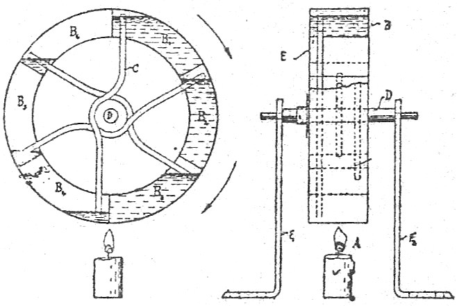
A disc, E, mounted on shaft, D, serves as support for six compartments; B1, B2, …B6, concentrically arranged about D. These, as well as the disc, can be made of tin soldered together. Two opposite chambers, for instance, B1, and B2, are connected by a small brass tube C, bent outward at the centre to clear the shaft, D, and projecting through the chambers nearly to the outer cylindrical wall. Two uprights, F1 and F2 support the wheel at proper distance over a small flame, A, or over a basin filled with hot water. One of each pair of chambers is filled with ether or acetone, while the other contains only the vapour of the liquid in an expanded state, but no air at all. The liquid is introduced into the chambers through small holes, and after the air has been blown out (by heating this liquid to the boiling point) each hole is sealed with a drop of solder.
Evidently, when one chamber passes through the hot one, the, liquid vaporises and passes through the tube to the opposite chamber, where it condenses. Thus the centre of gravity is constantly changed, causing the wheel to revolve. -R. V. Heuser, in the “Scientific American.”
(source: English Mechanic and Wold of Science, No 2302, 7th May 1909)


