


What is a Parametric design drawing
It is common drawing office practice, where a range of parts are similar, to produce a single drawing with a table of dimensions for the features of each separate component. The user will then need to sort out the appropriate sizes of each detail relating to the part required. The drawing itself being representative of a number of similar parts cannot be drawn true to scale for them all.
A study of Figure 1 will show a special screw, which has a family of parts. It is defined on a single drawing where the main dimensions are expressed algebraically as ratios of the shank diameter of the screw and other relevant parametric values. For a given thread size and screw length the CAD system is able to produce a true-to-size drawing of any individual screw listed. This drawing may then be used as part of an assembly drawing, or fully dimensioned and suitable for manufacturing purposes. Four typical screws are indicated at the right hand side of the illustration. It is always a positive advantage in design work to appreciate true sizes and uses them in layouts.
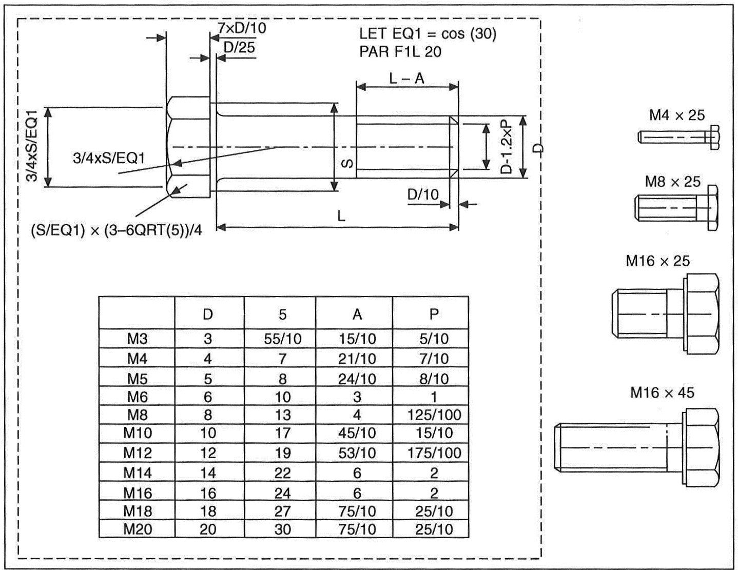
Figure 1
Components such as bolts, nuts, washers, fasteners, spindles, seals, etc., fall naturally into families where similar geometric features are present. The parametric capability of the CAD system can be used to considerably improve productivity in this area of drawing office work.
It is not uncommon practice in product development to modify existing standard components if possible and use them as the basis for new ones. Notice the visible connection between the features of the four components illustrated in Figure 2 køb cialis. This is a further example of parametrisation where the principles of variational geometry have been applied. The family of of parts is constructed from a large and small cylinder with different diameters, lengths and central bore sizes.
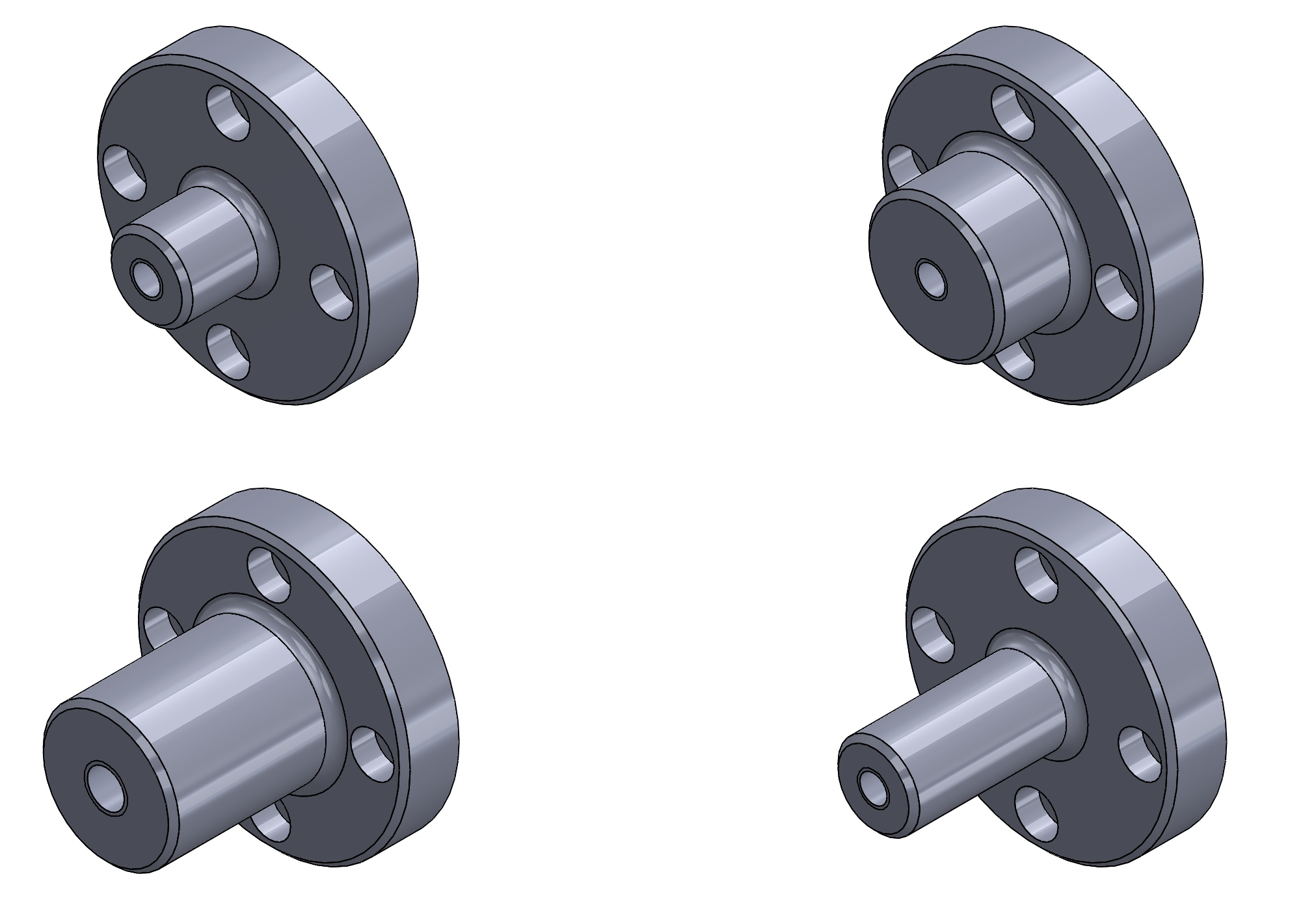
Figure 2
Parametric systems handle the full range of linear and angular dimensions including degrees and minutes. The computer will calculate maximum and minimum limits of size from specified tolerance values. Dimensions can be defined numerically or as algebraic expressions. You can avoid the need to dimension every fillet radius for example by setting a default value for radii. This means that unless a specific value is stated for a particular radius on a part that it will automatically be drawn at a previously agreed size. Where many radii are present, as in the case of casting work, this feature is a considerable aid to drawing office productivity. A number of such defaults can be entered, to cover a variety of applications.
Restoric Design is a professional drawing office based in the UK. We will create manufacturing drawings for a range of components. Please contact us on 01462 429 707 or info@jensen-consulting.co.uk for more information of our CAD Services.