CAD Services clarifies Exploded assembly drawings
There are a number of different drawing layouts available. The appropriate drawing layout should be chosen which illustrates the information in manner which is clear and best suited for the requirement. For example, there is no need to fully dimension every compoent in an assembly when the drawing is intended for general information or a spare parts list.
Depending on who will be using the drawing there are different layouts that should be considered, such as:
- Single-part drawing
- Collective single-part drawings
- Assembly drawings
- Collective assembly drawing
- Design layout drawings
- Combined detail and assembly drawings
- Exploded assembly drawings at-casinos.com
- Simplified drawings
- Machine Drawings (see article)
This article will give a short description on Exploded assembly drawings.
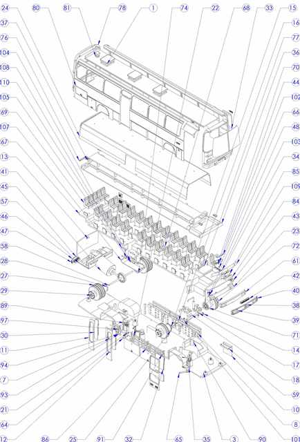
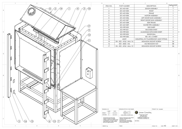
Figure 1 shows a typical explode assembly drawing; these drawings are prepared to assist in the correct understanding of the various component positions in an assembly. Generally a pictorial type of projection is used, so that each part will be shown in three dimensions. Exploded views are invaluable when undertaking servicing an maintenance work on all forms of plant and appliances. Car manuals and DYI assembly kits use such drawings, and these are easily understood. As well as an aid to construction, an exploded assembly drawing suitably numbered can also be of assistance in the ordering of spare parts; components are more easily recognisable in a pictorial projection, especially by people without training in the reading of technical drawings.
Further, exploded assemblies can also be animated to give a better understanding of all the components and interaction with each other.
Restoric Design is a UK based CAD Services. We produce a range of different drawing layouts best suited to your requirements. Please call us on 01462 429707 or email us at info@jensen-consulting.co.uk for more information.


