


Introduction
Google has indexed approx. 1 Trillion images. The growth of images on the internet is exponential. The rise of social media sites such as Instagram and Snapchat show the huge importance and increasing popularity of images on the internet.
The power of images for marketing is as old than marketing itself. However, changing technology and therefore the capability of creating outstanding product images has had an enormous affect on the type of product images used for marketing.
3D Product Visuals are graphics of products produced by a computer. Producing these Computer Generated Images (CGI) is an alternative to taking photos with a camera. 3D Product Visuals are used for marketing existing & non-existing products (concepts).
Increasingly company’s are using 3D Visuals of their products for their internet marketing campaigns. These photo realistic renders have several advantages compared to traditional photos:
- Presenting the product in its best possible “light”.
- Any Camera Angles possible – even gravity defying ones.
- 3D Sectional views – showing the produce sliced to present internal workings.
- In-Situ Drawings – showing the product in its installed environment.
This article is to give a short insight on how 3D Visuals are produced. This includes the information required, the tools used and the type of images produced.
Step 1 – Create a 3D CAD Model of the product
It is possible to create 3D Visuals of existing products (reverse engineering) by measuring/laser scanning or modeled as for concept from sketches (or similar). The first step of producing a computer generated image of a product is to produce a 3D CAD Model.
3D CAD Models are made by extending the 2D X-Y coordinate system with a 3rd Dimension Z. Any shape can be made – even those not achievable by conventional manufacturing methods (3D printing a side).

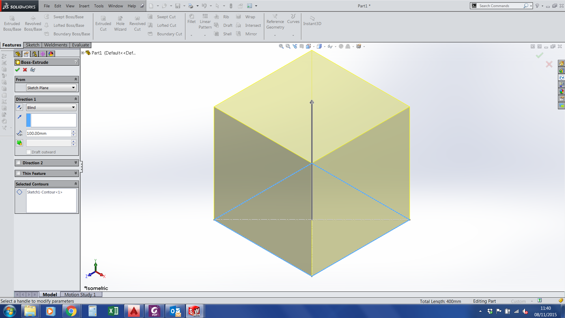
2D Sketch for 3D CAD Model
3D CAD Model Preview
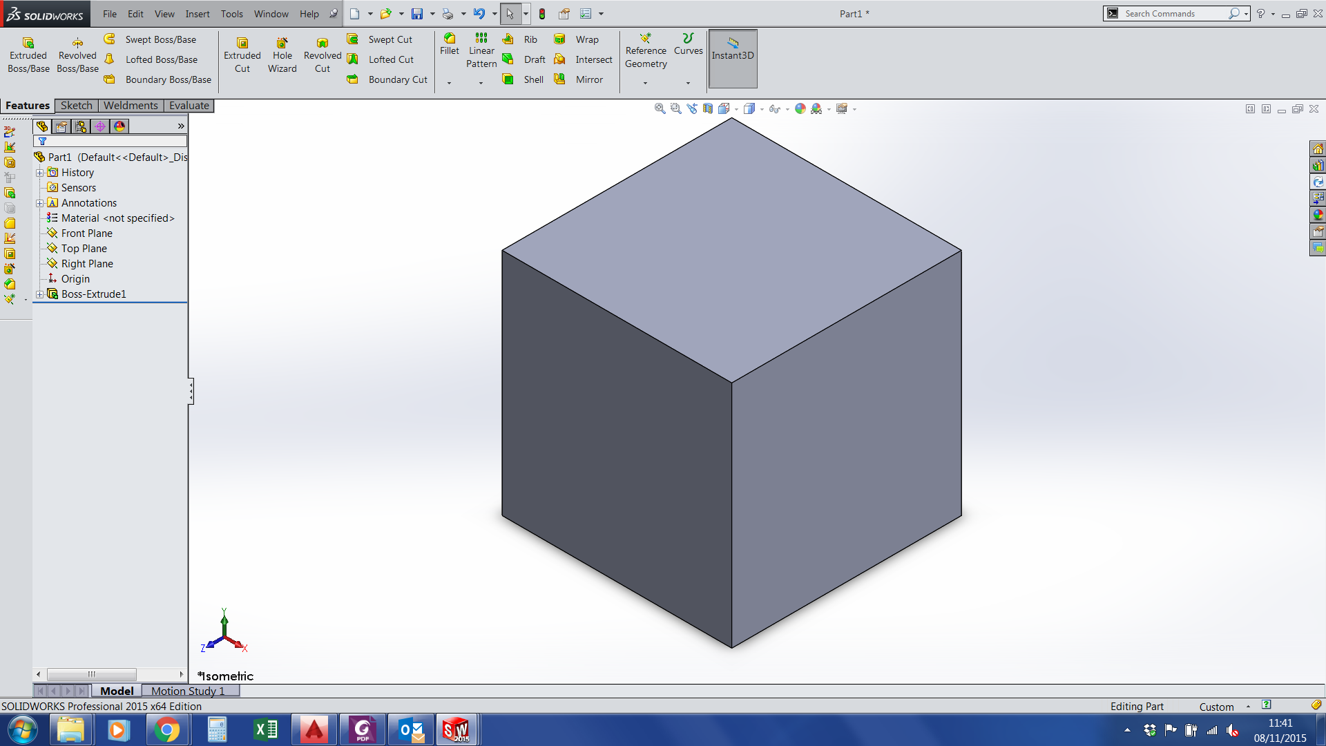
3D CAD Model of a cube
3D CAD Models are produced by Computer Aided Design Software such as Solidworks. To produce a basic shape, the first step is to create a 2D Sketch. This sketch in the x-y plane can then be extruded along the Z axis. The result is a 3 Dimensional shape. One can add more shapes to the existing or remove ‘material’ by cutting the shape.

3D CAD Model of a cube shelled

3D CAD Model of a cube shelled

Cut Extruded Cube
Step 2 – Import 3D CAD Model into a Rendering Software
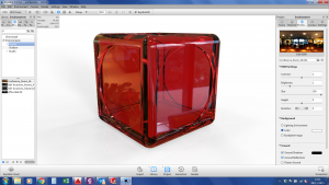
Once the 3D CAD Model has be created it can be exported and imported into a Product Rendering software such as Keyshot. Within the rendering software every single part requires its materials and finishes adding. Rendering packages come library of 100’s of different materials and finishes.
Once all materials have been assigned they get ‘fine tuned’ to get the best and most realistic appearance.
- Scale & direction of texture
- Refraction & Reflection Levels
- Brightness & Contrast
- Bump depths
are just a few variables used to set the materials.
The next step is to set the Environment. This includes setting up the
- Lighting (positions, direction & type of lights)
- Background
- Floor Reflections & Shadows

3D CAD Model imported into Rendering Software

3D CAD Model with material assigned
3D CAD Model with lighting changed
Restoric Design produces 3D Visuals. Not only does its 3D Product Visual Service produce excellent images, but also is able to create the 3D CAD Models required for importing into the Rendering Software Package.
For more information about our 3D Visual Services please contact Restoric Design on 01462 429 707 or contact us via email on info@jensen-consulting.co.uk.