What is CAD steel detailing?
Computer-Aided Designing involves processes such as definition translator, design and analysis algorithm, the definition of a geometric design, interface algorithms, and detailing. Steel detailing is a complex process that includes the creation of drawings for fabricators and contractors. These detailed drawings include plans and estimates, as well as essential reports.
Structural steel detailing
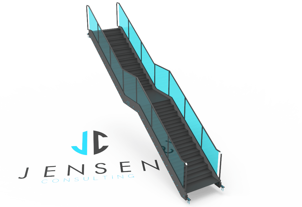
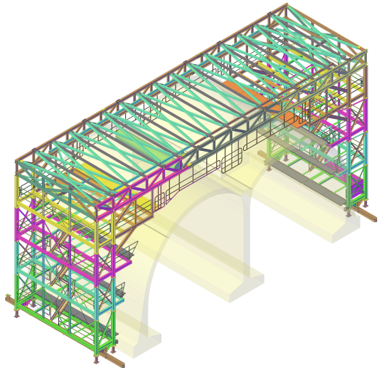
The process of structural steel detailing involves coming up with detailed design plans, architectural drawings for contractors, and other construction documents used for the production and erection of steel elements.
Structural steel detailing is the most efficient and error-free way of creating perfectly detailed working details. Steel detailing guarantees sophisticated and utterly perfect pre-fabricated building components when used by professional contractors and structural engineers.
The structural steel detailing process can be complicated, but that is a topic for another day. There are two main types of drawings that are universally recognised and used in structural steel detailing. They include fabrication drawings and erection drawing.
Fabrication drawing
Most people are familiar with fabrication drawing, which is commonly known as Shop drawing. Fabrication involves the positioning of every part and material particulars to the steel creation. To ensure efficiency in drawing, the most recent CAD software, such as AutoCAD, is used.
The software creates elaborate patterns to clearly explain design fabrication and align each steel element requirement with ease and sophistication. Why should you use Fabrication drawing for steel detailing?
It is time-saving, and who doesn’t know that time waits for no man? Fabrication drawing ensures that less time is spent even on the most complex processes. Also, you are guaranteed of accuracy while creating plans and drawings.
Finally, fabrication drawing is 99% error-free. Therefore, by using Fabrication drawing in steel detailing, you can be sure you are eradicating errors from your steel designs.
Erection drawing
Although erection drawing is not as popular as Fabrication, the results are equally great. Erection drawing is used to create CAD drawings and blueprint designs of steel erectors. The drawing design gives the exact data on the place and way of placing the steel components on the task at hand.
Erection drawing incorporates insight details on welding, bolts, wedges, and joints for the fabrications. Therefore, erection drawing saves the time spent on steel detailing while ensuring accuracy and perfect results.
2D vs. 3D CAD
Both types of drawings used in steel detailing involve the use of CAD software. However, how do you ensure you are getting the best by the use of CAD? You must have heard of 2D and 3D CAD and the debate around them.
While many steel detailing businesses, both big and small, are already benefiting from 3D CAD, the traditionalists are still stuck on the 2D CAD. Why the reluctance?
2D CAD still works and gets the job done at the end of the day. By shuffling between drawings, the steel detailer can get the creations completed at the end of the day. However, even though 2D functions, it is not half as accurate as of the new 3D CAD.
Why should you change to 3D CAD?
The efficiency that comes with 3D CADs goes without saying. You can save money and time while using these CADs due to the improved efficiency.
Also, 3D CADs enables the user to compete with other businesses since they are not limited. A 2D CAD can only be used with fabricators and erections that are 2D, therefore caging the detailer.
While using 2D CADs, there can emerge different interpretations of the drawing, which can result in grievous mistakes. However, using 3D CAD eliminates any chances of costly errors. 3D CAD significantly improves steel detailing while keeping the business abreast of any evolution.


