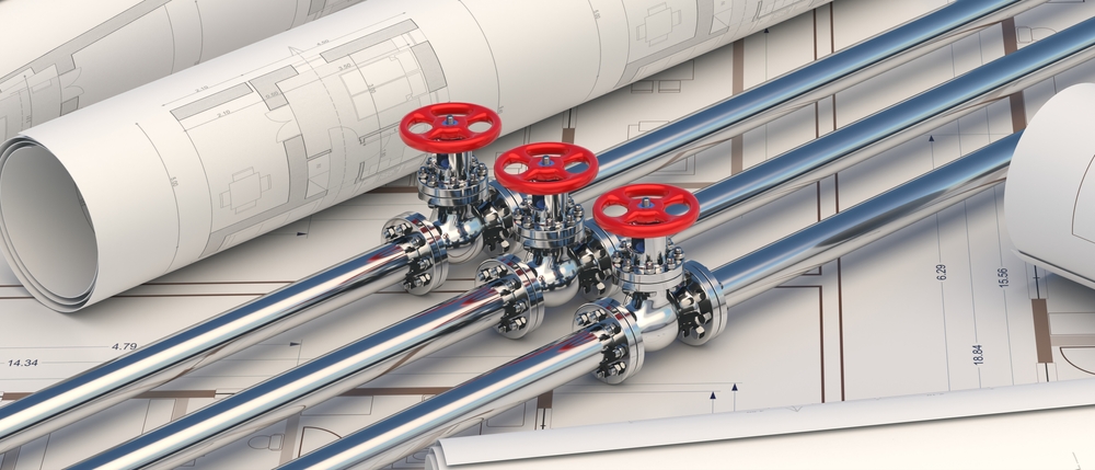
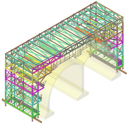
Isometric drawings are used by plumbers, engineers and designers to depict pipework and plumbing systems in 3D. It’s important to make a plumbing sketch before any work is done and this is a vital step in the design process to illustrate the proposed plumbing layout. Isometric drawings require a specific skill set and need to follow certain rules. In this guide, we take a look at how to draw isometric drawings for plumbing and some top tips for creating useful and detailed plumbing drawings.
What are isometric drawings?
An isometric drawing is a 2D sketch which looks 3D due to the use of specialised drawing techniques. Also known as isometric projection, these detailed drawings are a great way to represent a 3D object or building on a 2D surface to scale. They can be complex to draw but they are the best way to communicate information about plumbing.
Residential building plans don’t usually include an isometric drawing for plumbing, so it might be wise to hire a professional architectural drawing company. Isometric sketches are a type of axonometric drawing, which means the same scale is used on every axis.
Isometric plumbing sketches
The point of an isometric plumbing drawing is that someone else could install the plumbing correctly using just the plan. With clear measurements and standardised rules, this is a practical way of using mathematics and geometry to create an accurate design.
The 2d drafting process has many benefits and these detailed drawings can be great for showing investors, tradespeople and architects the intended location of pipework and fixtures. Because the drawing is to scale, you can take actual measurements of the plumbing and pipework and you can also add more information such as the size of the pipes and the dimensions of plumbing fittings.
Isometric sketching rules
There are certain rules you must follow when making an isometric sketch for plumbing, whether you’re using paper and a pencil or CAD software. These include the following:
• When making an isometric sketch, vertical lines stay vertical and horizontal lines are drawn at 30 degrees to the horizontal plane.
• If you’re drawing circles in an isometric sketch, you will have to use an ellipse.
• Parallel edges are drawn as parallel lines.
• If pipes are at an odd angle rather than horizontal or vertical, you would use a 60-degree angle to depict this.
• Draw the isometric drawing as if you were at the lowest point of the plumbing system.
• If you’re drawing on paper, you can use an isometric grid to make sure everything is correctly aligned. Preprinted isometric drawing paper has dots to use as points.
• To create an isometric drawing, you will need isometric paper, a pencil, a ruler and a protractor.
CAD for plumbing schematics
Thanks to advancements in Computer-Aided Design, mechanical engineers, plumbers and designers can use software to create a plumbing plan. This can be a quicker and easier way to create isometric drawings for plumbing but it does also require knowledge of the software. Most CAD programmes have an isometric drawing option which you can select, as well as specialist plumbing layout tools. You can also add accurate measurements to your sketch which means the drawing can easily be scaled up.
Get in touch
If you need a detailed plumbing drawings for your project, at Restoric Design, we can provide both paper and digital isometric drawings. Our experienced design team are here to make the whole process simple, so call us today on 01462 514 300.


